Bridge Design Challenge Rules
You are going to design a bridge in Autodesk Fusion, print it in PLA, and load it until it breaks. The bridge that holds the most weight does not win. The bridge that holds the most weight for its own weight wins. These are the rules, numbered so you can cite them.
The Test Rig
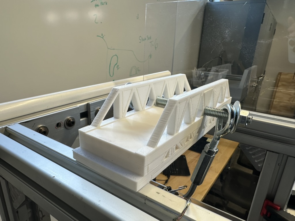
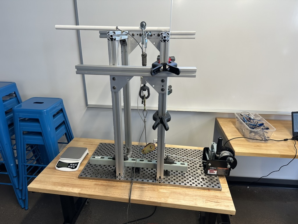
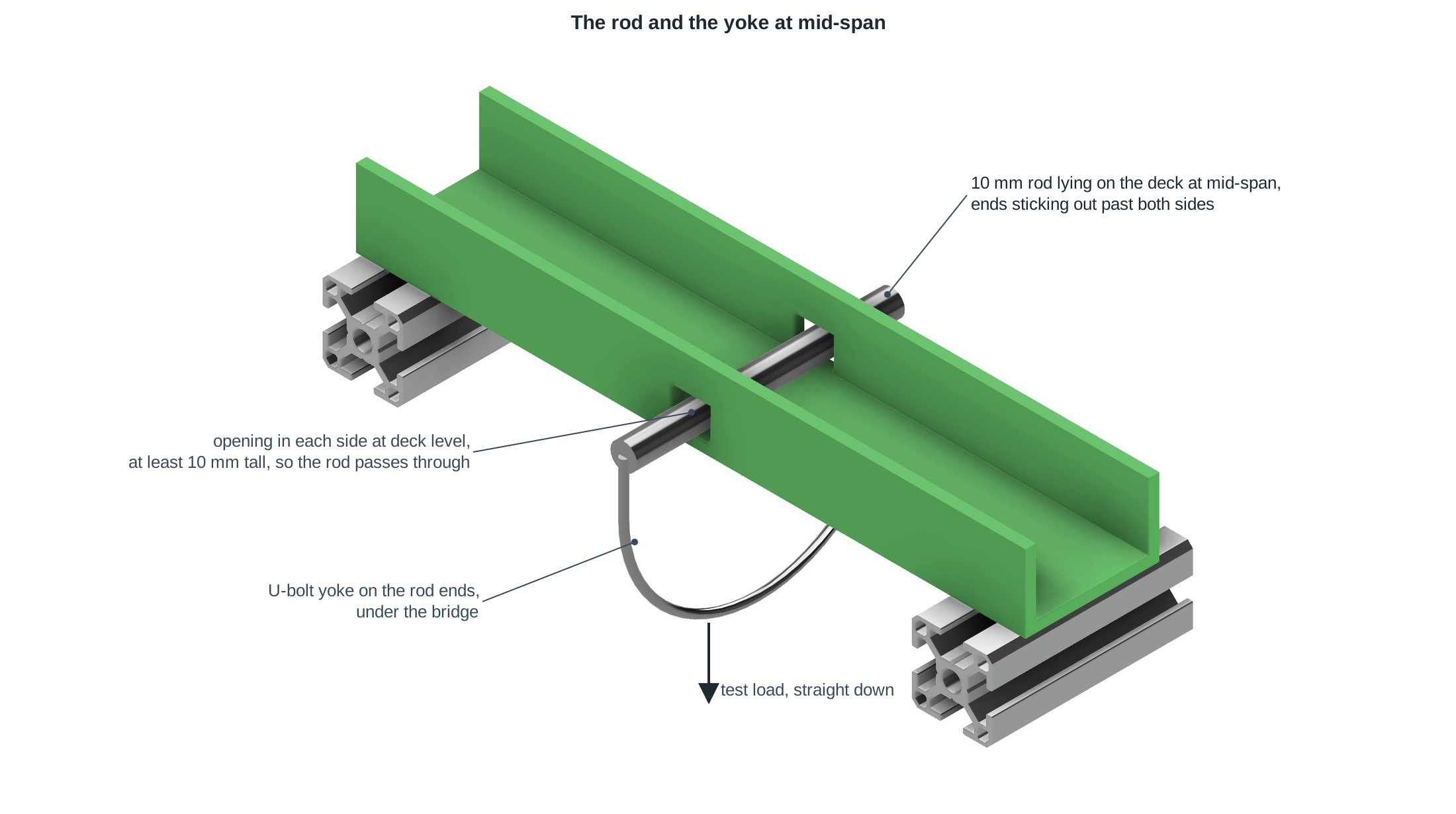
The rig is a T-slot aluminum tower with two piers 200 mm apart. Your bridge rests on the tops of the piers and is not clamped, so it has to reach far enough onto each pier to stay put. A 10 mm steel rod lies across the deck at mid-span. The rod's ends connect to a yoke under the bridge, and a hand-cranked winch pulls the yoke straight down through a load cell while a string potentiometer measures how far the deck moves. Force and deflection are recorded at 1,000 samples per second until the bridge fails.
The rig may change
The rig might be rebuilt to push the rod down from above with a linear actuator instead of pulling it from below with a cable. The 200 mm span, the 10 mm rod, and every dimension below will not change, so design to the rules, not to the photo.
Building the Bridge
-
The bridge is designed in Autodesk Fusion.
-
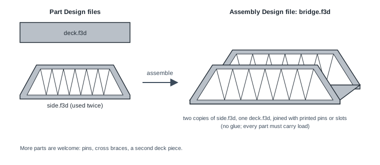
The bridge is an Assembly Design built from at least two Part Design files: a deck and a side. If your sides are mirror images, design one side part and use it twice in the assembly. More parts are welcome, and so are pins, braces, and cross members.
-
Every part must carry load. A part that could be deleted from the assembly without weakening the bridge does not count as a part.
Why the deletion test
A single solid body with a small extra piece pinned on satisfies the letter of a "multiple parts" rule and none of its purpose. Real structures are assembled from parts that are designed, made, and fitted separately, and that is the skill this project builds. If you can delete a part and nothing changes, it was decoration.
-
Dimensioned 2D drawings of the bridge must be submitted and approved by Mr. Willis before anything is printed. The drawing set shows top, side, and cross-section views and an isometric view, with dimensions.
-
Bridges are printed on the NPA Engineering printers with the PLA filament provided.
-
The whole bridge, support material included, uses no more than 200 g of filament as reported by PrusaSlicer.
-
The whole bridge prints in no more than 5 hours as reported by PrusaSlicer, totaled across all of its parts.
-
Parts are joined only by 3D printed mechanical connections: pins, slots, snap fits, dovetails, and the like. No adhesive, no tape, no fasteners, no foreign material, and no reheating or re-extruding filament after printing.
Dimensions
The piers set the shape of the problem. Everything below is measured from the pier bearing level, the flat top of the piers where the bridge rests.
-
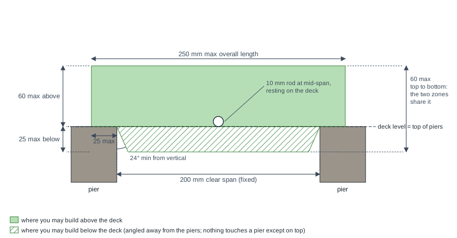
The bridge is free-standing and spans two piers 200 mm apart. The span is fixed and will not change.
-
The overall length is no more than 250 mm, which leaves up to 25 mm resting on each pier.
-
The bridge is at least 50 mm wide and no more than 75 mm wide, so the rod can reach the yoke on both sides.
-
The bridge is no more than 60 mm tall from its lowest point to its highest point, and no more than 25 mm of that may hang below the pier bearing level. A bridge that uses all 25 mm below the piers has only 35 mm left above them.
-
Nothing on the bridge touches a pier except on the pier's top bearing surface, before or during the test. Anything that hangs below the bearing level must angle away from the pier's inner face by at least 24° from vertical, as shown in the figure. The angle is there so the bridge can bend under load without its underside swinging into the inner edges of the piers; a bridge that touches an inner edge during the test has failed at that moment (rule 26).
The Deck and the Road Test
The deck is the road. A bridge without a road is a beam, and beams are not what we are building.
-
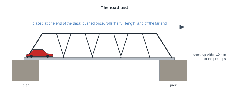
A deck runs the full length of the bridge and is at least 50 mm wide. Its driving surface is no more than 10 mm above the pier bearing level, so the road sits at ground level, not on top of a wall. The deck may be any thickness and may be made of more than one piece.
-
The driving surface is smooth and continuous, open to the sky, with no holes, curbs, bumps, or seams that a wheel can catch on. Sides, railings, and trusses stand outside the 50 mm driving lane, never in it.
-
The road test. Before a bridge is weighed or loaded, a standard Hot Wheels car is placed at one end of the deck and pushed once. It must roll the full length of the deck and off the far end without being lifted, steered, or stopped. A bridge that fails the road test is not load tested and receives no efficiency or stiffness score.
The brick
A solid block with a flat top 55 mm above the piers would hold a great deal of weight, and it would not be a bridge. Rules 14 through 16 keep the road at ground level, and the road test is how we check.
The Rod
-
A 10 mm diameter rod lies across the deck at mid-span, resting on the driving surface, with its ends sticking out past both sides of the bridge. Nothing on the bridge may touch the rod except the deck it rests on. In practice this means the sides of your bridge need an opening at deck level at mid-span, at least 10 mm tall, so the rod can pass through.
-
The test load is applied to the rod, straight down. The deck carries it into the rest of the bridge; how it gets from there to the piers is your design problem.
Load
The load rules are built on the bridge's actual traffic, with a margin.
-
Design load: 200 g. A standard Hot Wheels car is 57 to 90 mm long, up to about 32 mm wide, and weighs 36 to 40 g. A 250 mm deck holds at most four short cars bumper-to-bumper in one lane, about 160 g, rounded up to 200 g. That is the most traffic the bridge will ever see.
-
Safety factor: 10. Real bridges are designed to carry several times their expected load, because materials have flaws, loads get misjudged, and things wear out. A safety factor is the ratio of what a structure can hold to what it is expected to hold. Ours is 10.
-
Proof load: 2 kg (design load times safety factor; about 20 N). Every bridge must hold the proof load without breaking or slipping off the piers. A bridge that cannot hold 2 kg is not scored for efficiency or stiffness.
Why a floor and not a target
Two kilograms is not hard. A decent PLA truss holds many times that. The proof load is there to catch a bridge that is all cleverness and no strength, and to give the stiffness measurement one fixed load every bridge sees. The real contest is the ratio below.
Scoring
Every bridge is weighed on the rig's scale before testing. Weight includes the deck and every part of the assembly.
-
Design (10%). The quality of the drawing set, the assembly, and the fit and finish of the printed parts.
-
Efficiency (45%). Failure load divided by bridge mass, both in grams, so a 100 g bridge that holds 10 kg scores 100 and a 200 g bridge that holds 15 kg scores 75. The lighter bridge wins even though it held less. Doing more with less is the point.
-
Stiffness (45%). How much the load grows between the 200 g design load and the 2 kg proof load, divided by how far the deck moves between those two loads, then divided by bridge mass. Starting the measurement at 200 g instead of zero lets the rod, yoke, and bridge settle before the clock starts. In grams and millimeters: a 100 g bridge whose deck moves 0.5 mm between 200 g and 2,000 g scores 1,800 ÷ 0.5 ÷ 100 = 36, and a 200 g bridge that moves the same 0.5 mm scores 18. Higher is better. A bridge that sags under a light load is doing something wrong even if it eventually holds a lot.
-
Efficiency and stiffness are scored relative to the class: the best bridge in each category sets the top score, and every other bridge is scored in proportion to it.
-
Failure is the moment the bridge is no longer holding itself up on the tops of the piers: it breaks, a part lets go, it slides off, or any part of it touches an inner edge of a pier. The failure load is the highest load recorded before that moment.
The Rules on One Card
| Rule | Limit | Checked how |
|---|---|---|
| 2, 3 | Assembly of at least a deck part and a side part; every part carries load | Fusion files |
| 4 | Dimensioned drawings approved before printing | Drawing review |
| 6, 7 | 200 g of filament, 5 hours of printing | PrusaSlicer |
| 9, 10 | 200 mm span, 250 mm max length | Tape measure |
| 11, 14 | 50 to 75 mm wide, deck 50 mm wide the full length | Calipers |
| 12 | 60 mm tall overall, at most 25 mm below the piers | Calipers |
| 13, 26 | Nothing touches a pier but its top, even under load; 24° relief below deck | Fit on the rig, then the test |
| 14 to 16 | Driving surface within 10 mm of pier level, smooth, open | The road test |
| 17 | 10 mm rod lies on the deck at mid-span, through the sides | Rod fits |
| 21 | Holds the 2 kg proof load | Load test |
| 22 to 24 | Design 10%, efficiency 45%, stiffness 45% | Test data |