Assemblies and Joints
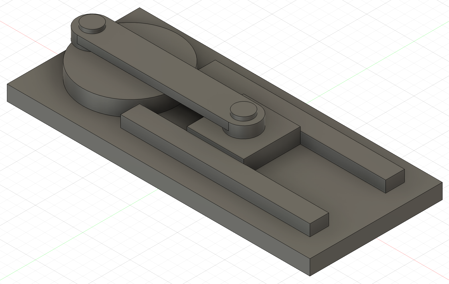
Every piston engine in the parking lot runs on the mechanism you're about to build. A slider-crank turns a spinning wheel into a straight back-and-forth push, or the reverse: in a car, the piston is the slider, and it shoves the crank around a few thousand times a minute. Ours has six parts, no fuel, and a top speed of however fast you can drag a mouse.
Overview
Every design you've made so far has been one part. Real products are several parts that fit together and move against each other, and Fusion builds them in an assembly: a design made of separate components held together by joints, each of which says how two components may move relative to each other. You'll put six premade parts together into a working slider-crank using three kinds of joint (rigid, revolute, and slider), then operate it by dragging the crank.
Builds on: Expired Patent Project — the Data Panel, saving designs, and moving around a model with the ViewCube.
Before you start
Sign in to Autodesk Fusion and open the Data Panel. You'll start by making folders, not models.
You've got it when…
- Your
Slider Cranklab folder holds aPartsfolder with the six parts, and yourSlider Crankassembly sits beside it. - Your
Slider Crankdesign holds all seven components (six parts, with two copies of the Pin), and only the Base is grounded. - The Browser lists seven joints by name: Axle-Base, Crank-Axle, Slider-Base, Pin-Crank, Pin-Slider, Rod-Crank, and Rod-Slider.
- Dragging the crank turns it, the connecting rod follows, and the slider moves back and forth between the rails.
Collaboration & AI
Work: On your own. Ask a neighbor when your screen doesn't match the lab, but build your own assembly.
AI — AIAS Level 1, No AI: This lab teaches the joint tools by having you use them, so set AI aside. What the levels mean.
Set Up Your Lab Folder
The six parts you'll assemble are already modeled and waiting in Class Files. Your assembly needs its own copies, organized in a folder of its own, before you build anything.
-
In the Data Panel, open your Fusion student folder and create a new folder named
Slider Crank. This is your lab folder; everything for this lab goes in it. -
Open your
Slider Crankfolder and create a folder inside it namedParts. -
Browse to Class Files ▸
tutorials▸Assembly Tutorial▸Parts. It holds six parts: Axle, Base, Connecting Rod, Crank, Pin, and Slider. -
Right-click the Axle, choose Copy, and select your own
Slider Crank▸Partsfolder as the destination. -
Repeat step 4 for the other five parts. Open your
Partsfolder and confirm all six are there. -
Create a new Assembly Design.
-
Save it right away as
Slider Crank, in yourSlider Cranklab folder and not inParts. Your lab folder should look like this.One folder per project, assemblies above their parts
This is how engineers keep a project findable. Every project gets a folder of its own, so nothing from one project wanders into another. Inside it, the assembly sits one level above a folder of the individual parts it's built from, like a Lego instruction booklet sitting on top of the bag of bricks it calls for. Like the booklet, the assembly doesn't hold the parts; it refers to the part files and says where each one goes. Keeping those files in a folder right beside it means the project stays together when you open it next month, share it, or add a part. Do this for every project from here on, not just this one.
Connect the Axle to the Base
The first joint is the simplest: two parts locked together so they can't move at all. It's also where you'll learn the routine every other joint follows.
-
Find the Base in your Parts folder. Right-click it and select Insert into Current Design, or simply drag it into your
Slider Crankdesign.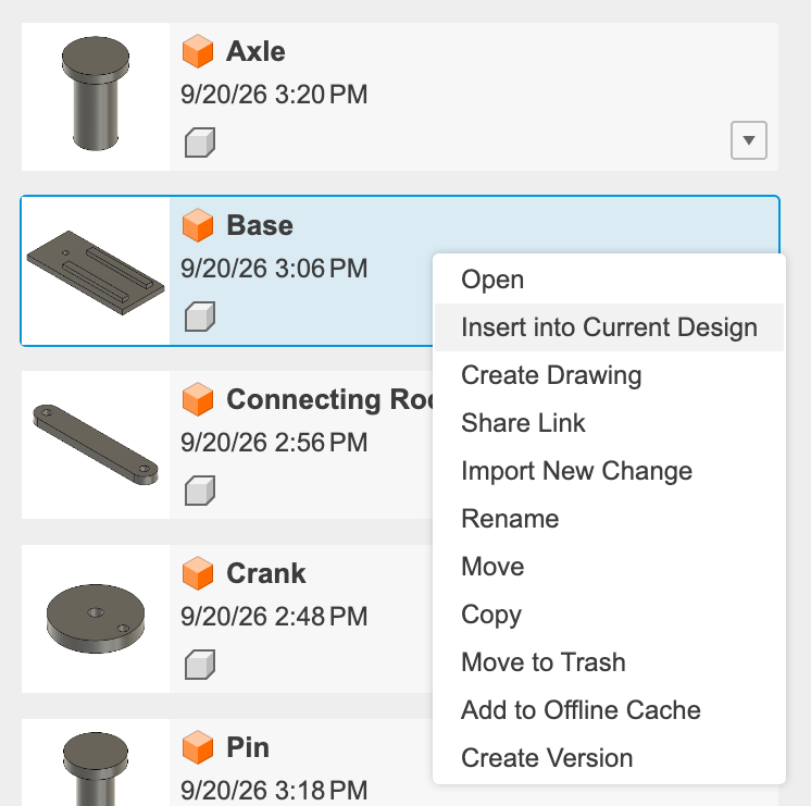
-
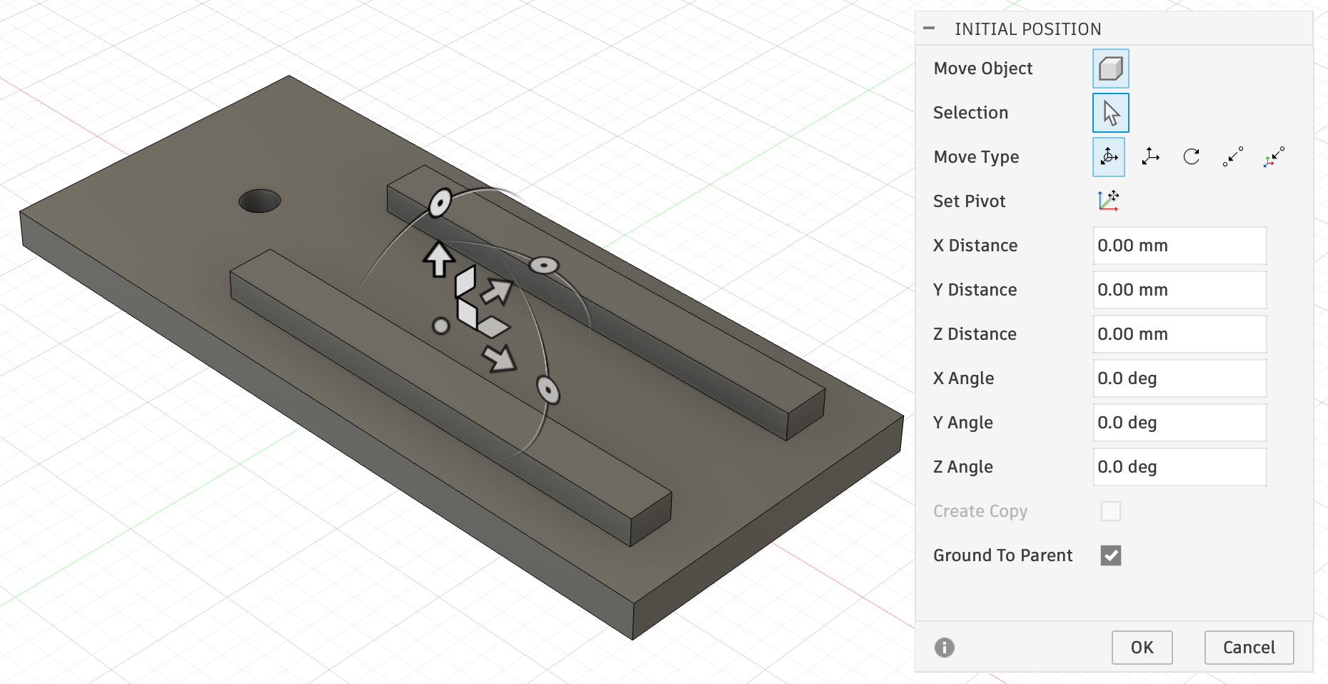
Leave the Base at the default initial position. Notice that Ground To Parent is checked for the first inserted part by default. A grounded component is locked in place, and the other parts will move relative to it. Click OK.
-
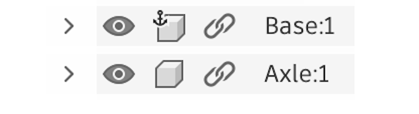
Notice that the Base in the Browser shows a small anchor icon, indicating that it is grounded to the parent. You can right-click a component in the Browser to turn grounding on or off. An assembly needs at least one grounded component; in this case, we want to leave it on.

-
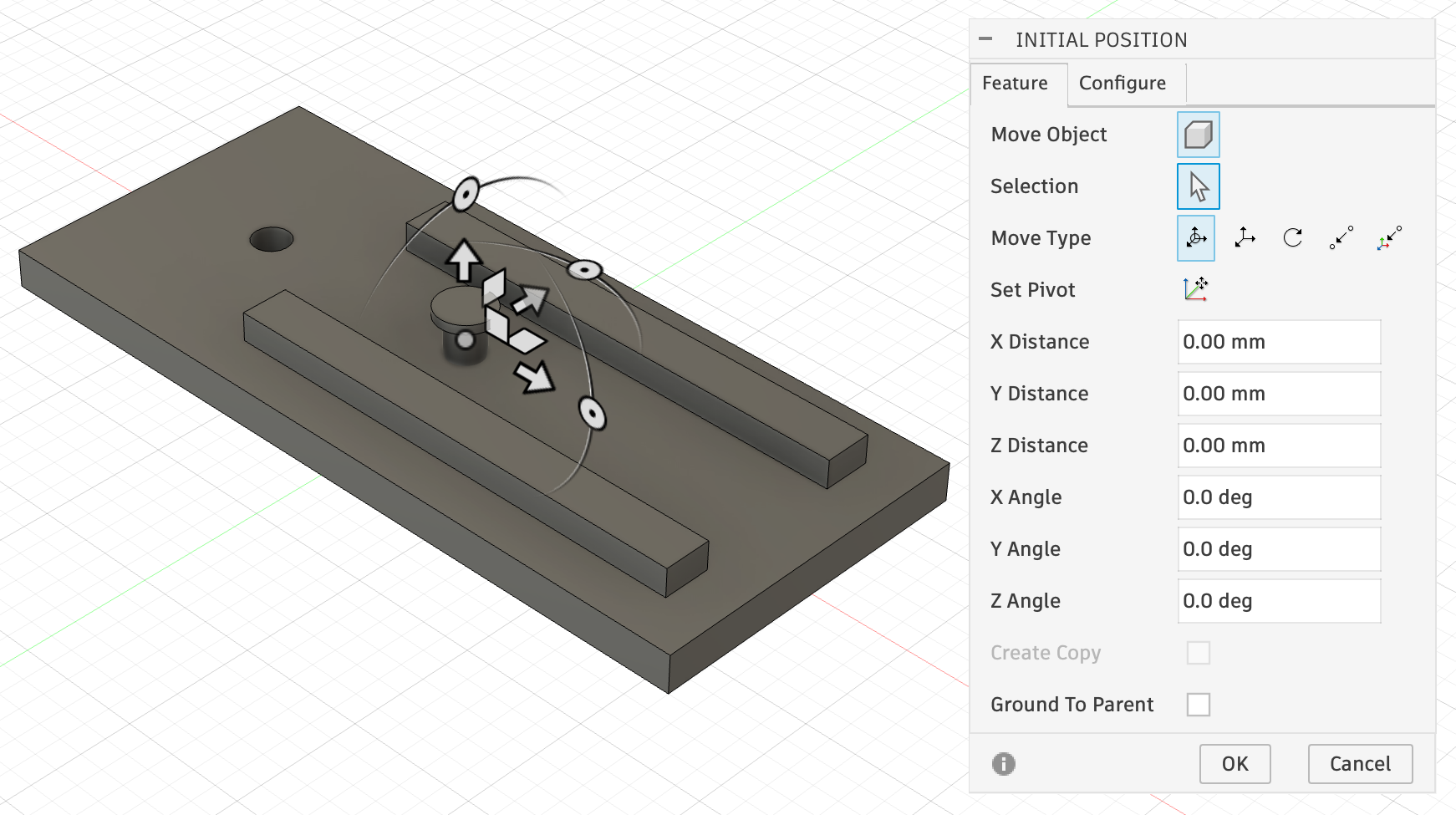
Find the Axle in the Parts folder and add it to the design. Be sure the checkbox for Ground To Parent is not checked, leaving this part free to move. Click OK.
-
Notice that the Axle does not have an anchor icon in the Browser, because it is not grounded and is free to move. If yours is grounded, right-click it and unground it now.
-
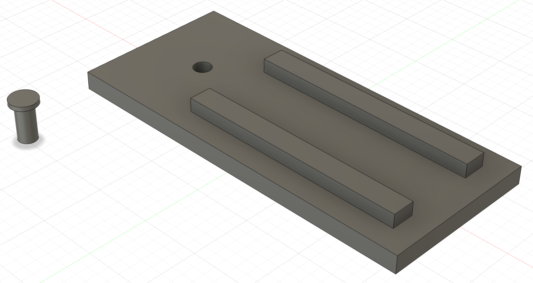
Drag the Axle to one side so it is away from the Base. Place it anywhere that lets you see both parts separately.
-
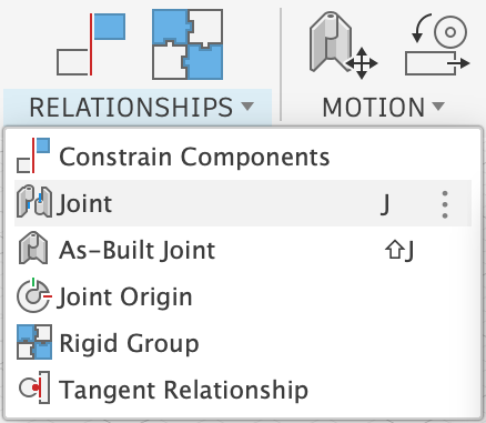
Select Relationships ▸ Joint, or press J.
-
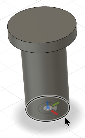
Select the circular bottom edge of the Axle. The part turns partially transparent when you click the edge, to show that the first component has been selected.
-
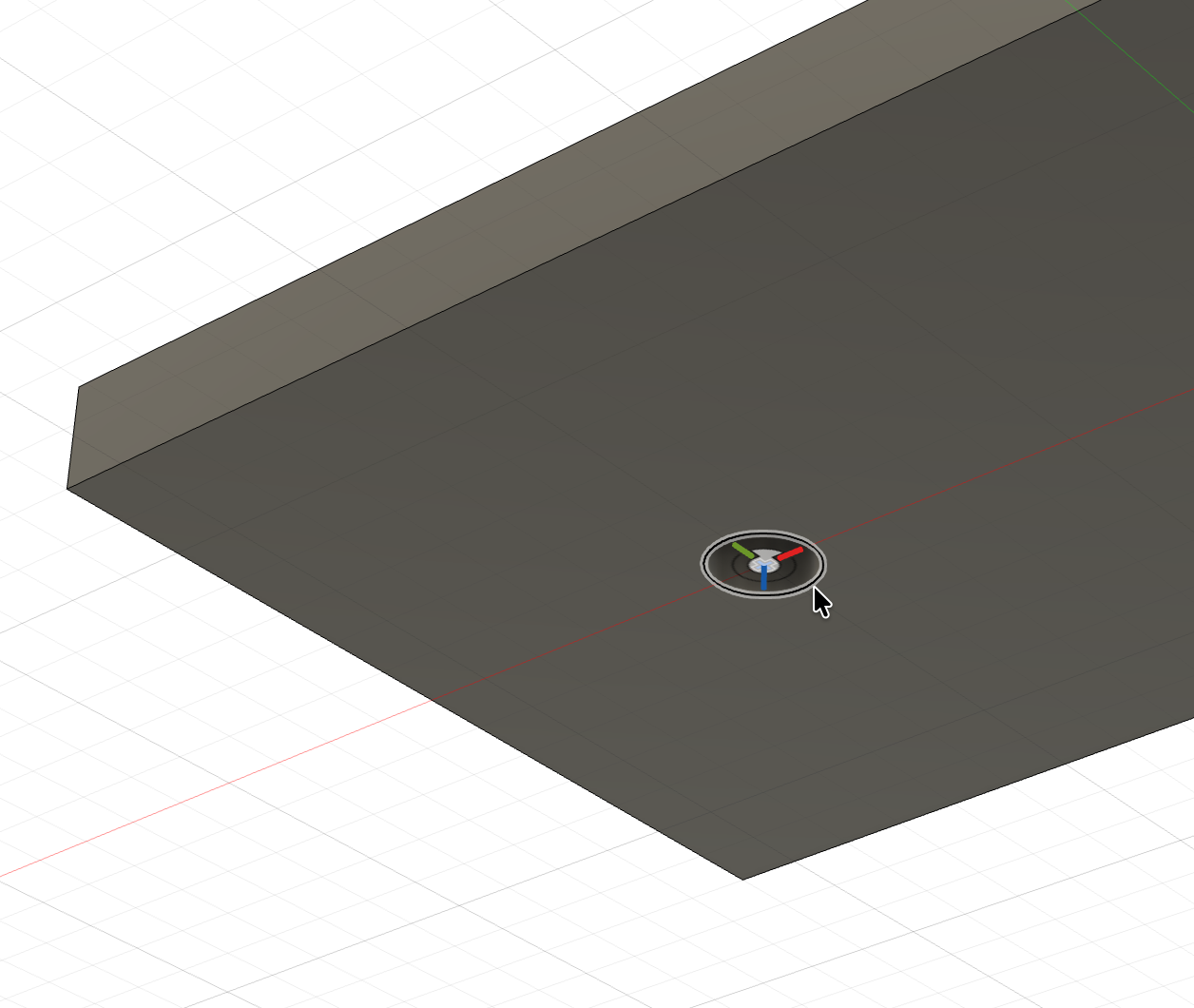
Orbit your view so you can see the bottom of the Base. Select the circular edge of the hole in the Base. Fusion joins the parts together at the edges you selected.
-
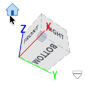
Click the Home button above the ViewCube to return to the view from above.
-
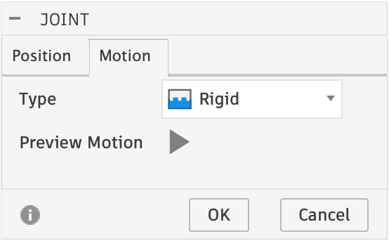
Select the Motion tab and set the Type to Rigid. Press the Preview Motion play button. Fusion shakes the joined parts to show that they are rigidly connected. Click OK.
Rigid joints
A rigid joint allows no motion at all; the two parts behave as if they were glued. It's the right joint for anything pressed, bolted, or welded together, like our Axle in its hole.
-
Try to drag the Axle. It won't move; it's rigidly connected to the Base, and the Base is grounded.
-
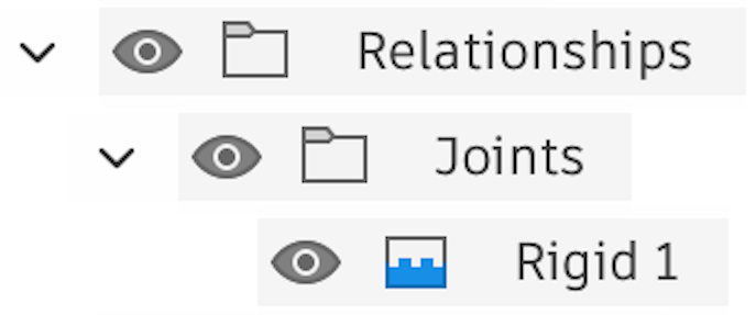
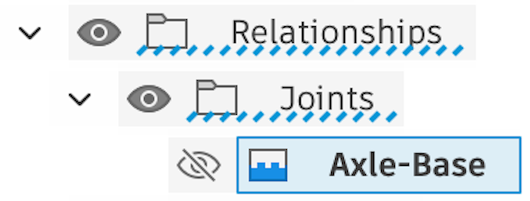
Expand the Relationships and Joints folders in the Browser.
-
Double-click the joint's label and rename it Axle-Base, then click the eyeball icon next to it to turn off the joint icon display in the design.
Tip
It's a best practice to rename each joint as you create it. Seven joints named "Rigid 1" through "Revolute 4" are a guessing game; seven joints named for the parts they connect are a parts list.
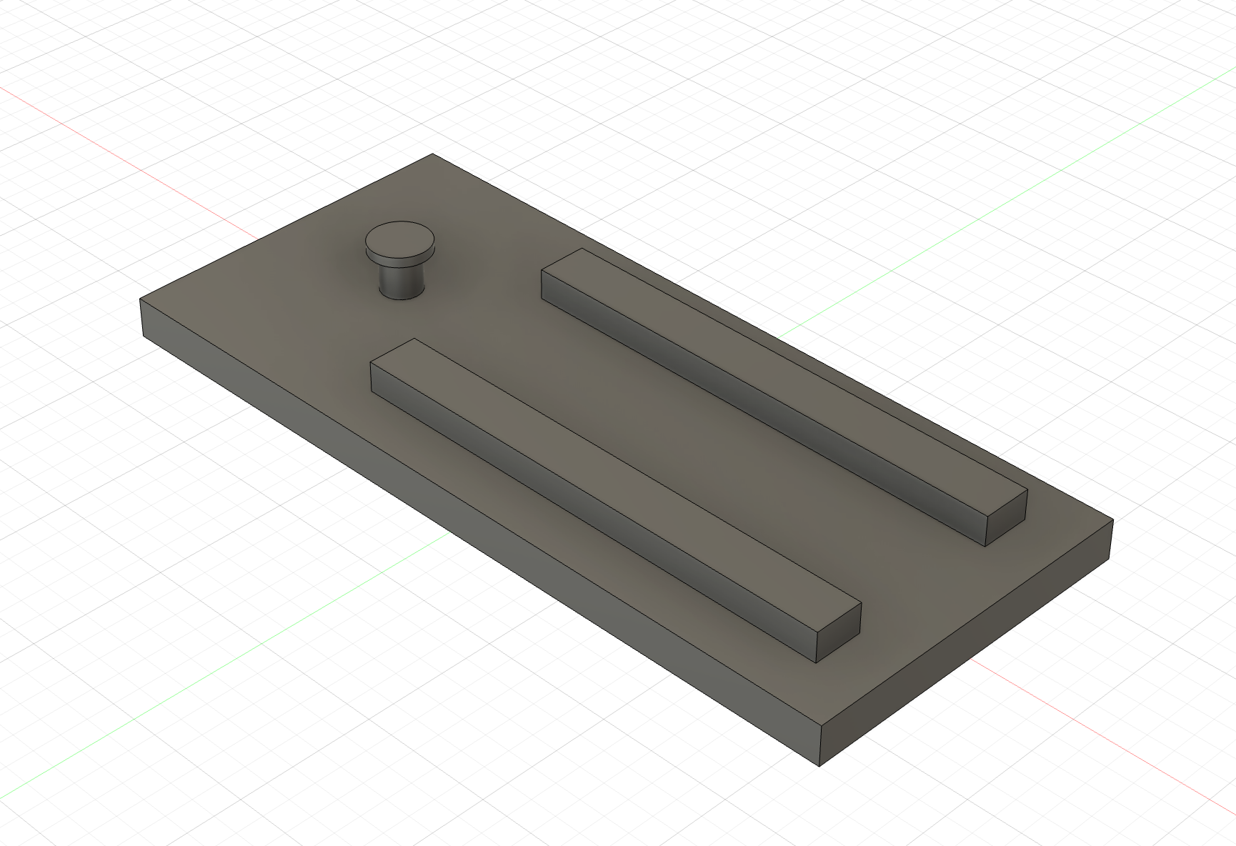
Your model should look like this.
Connect the Crank to the Axle
The steps in the following sections use different joints and move a little faster. Look back at the previous section if you need a reminder of how to do a specific step.
-
Find the Crank in the Parts folder and add it to the design, making sure that Ground To Parent is not checked.
-
Click the eyeball icon next to the Base to hide it temporarily.

-
Select Relationships ▸ Joint or press J.
-
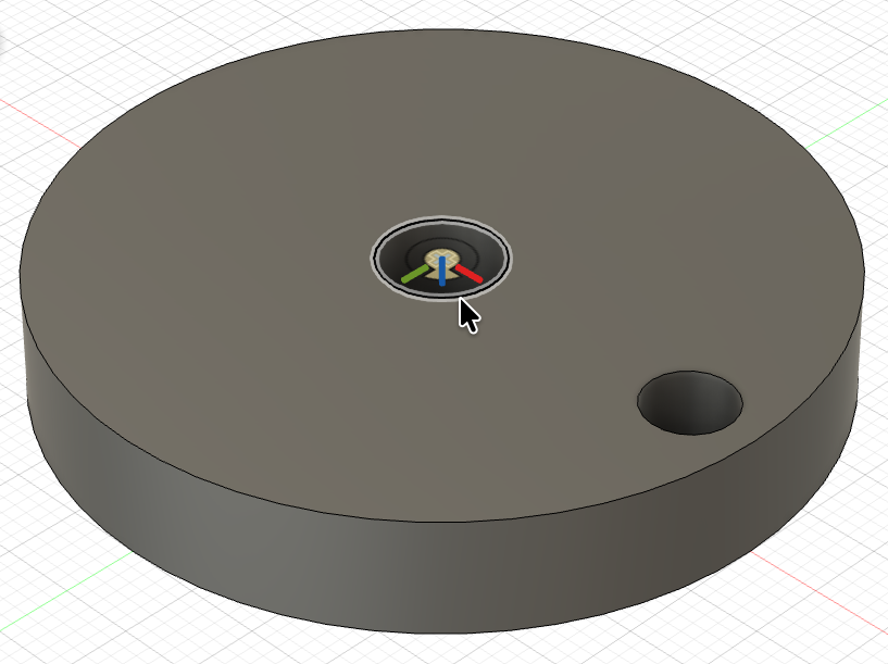
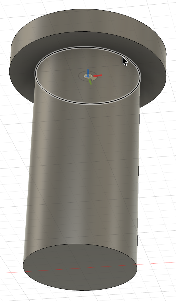
Select the upper edge of the center hole in the Crank, then the edge underneath the head of the Axle.
-
On the Motion tab, set the Type to Revolute. Click the Preview Motion play button to watch the Crank revolve about the Axle. We could also set limits on the rotation here, but we want the Crank free to turn all the way around. Click OK.
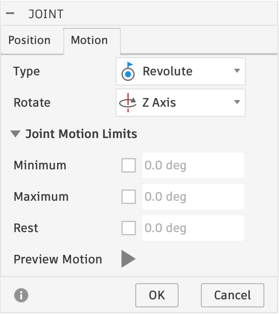
Revolute joints
A revolute joint allows rotation about one axis and nothing else, like a door on its hinges or a wheel on its axle.
-
Rename the joint Crank-Axle and hide it in the design.
-
Click the Base's eyeball icon to show the Base again.
You can now operate the Crank by grabbing it with your mouse and dragging it around. Your model should look like this.
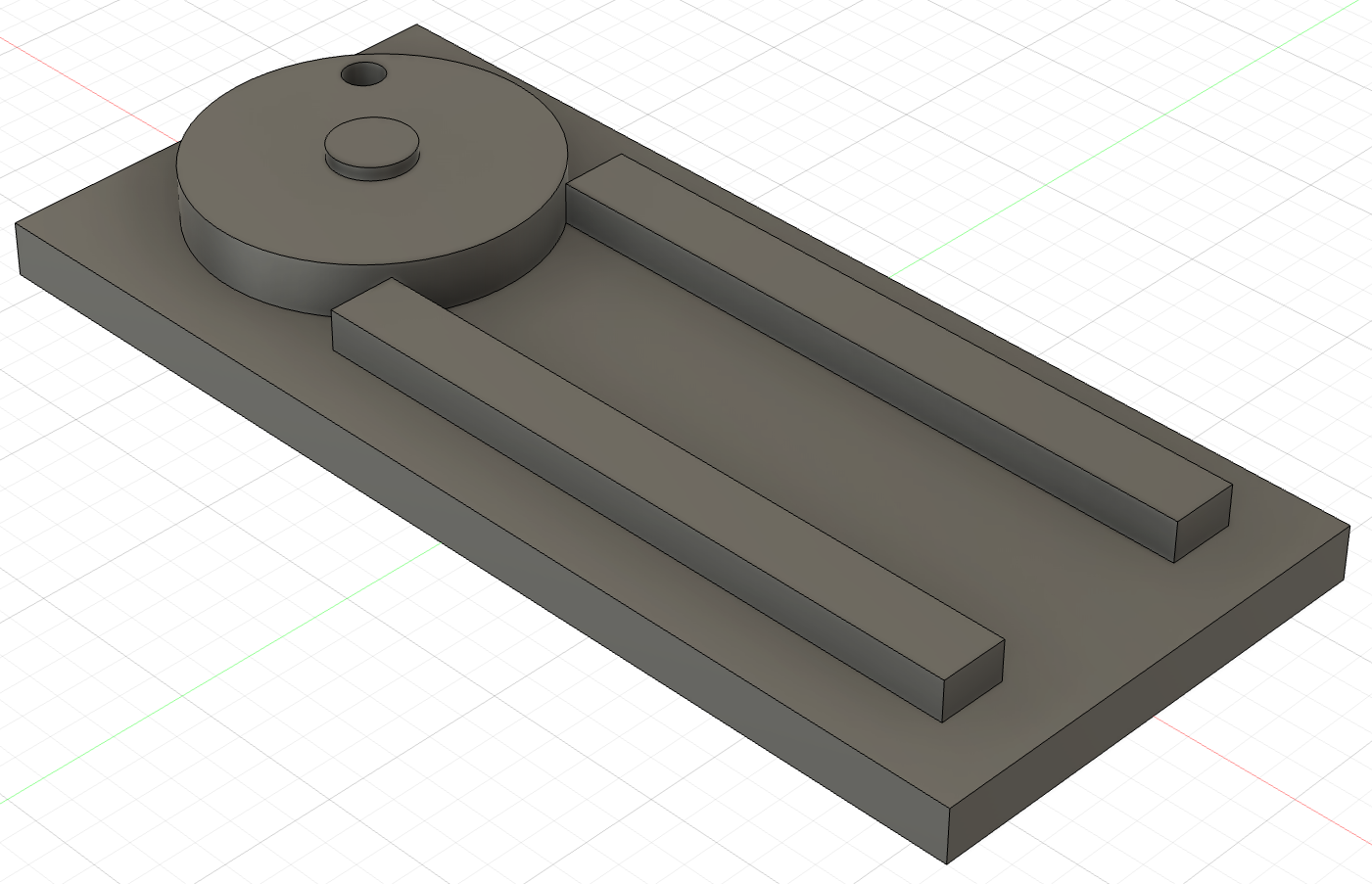
Add the Slider
The Slider is 28 mm wide, and the gap between the Base's guide rails is 30 mm, which leaves a little clearance. Instead of joining a hole to a hole, this joint lines up the middle of an edge on the Slider with the middle of an edge on a rail.
-
Find the Slider in the Parts folder and add it to the design, making sure that Ground To Parent is not checked.
-
Hide the Base.
-
Select Relationships ▸ Joint or press J.
-
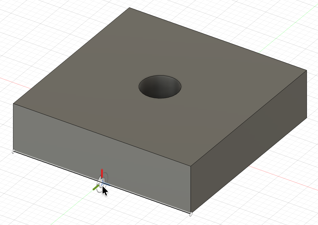
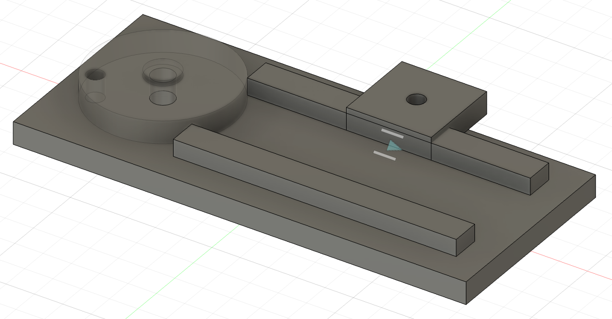
Hover your mouse over the middle of the Slider's near-side lower edge until the target snaps to the midpoint, then click to set it as the Component 1 snap point, the exact spot on a part where a joint attaches.
-
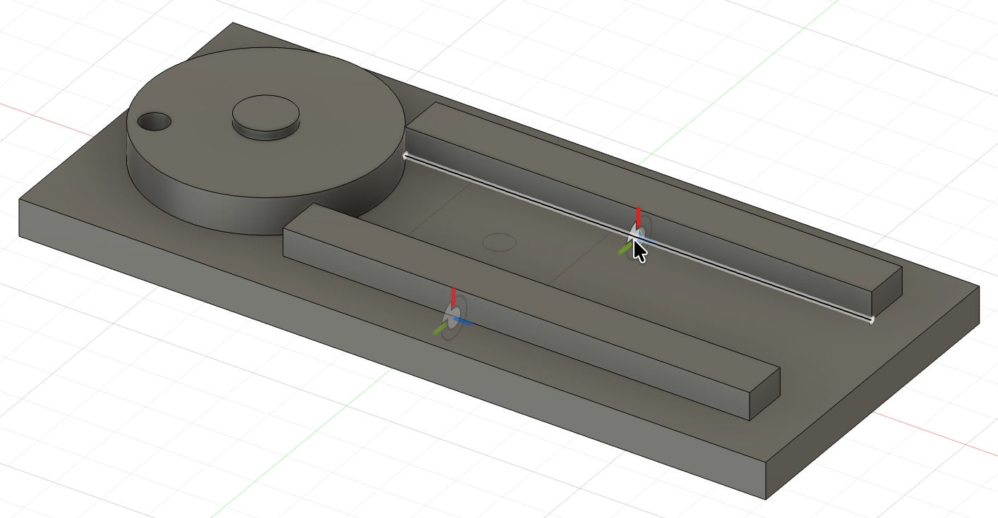
Show the Base and select the midpoint of the far rail's lower inside edge as the Component 2 snap point.
-
On the Motion tab, change the Type to Slider. If the Slider's direction arrow doesn't point along the rails, change the axis with the Slide setting.
Slider joints
A slider joint allows movement in a straight line along one axis, like a drawer on its runners.
-
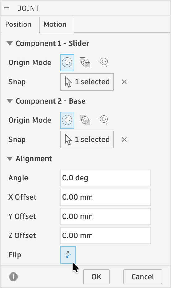
The Slider is on the wrong side of the far rail. Return to the Position tab on the Joint panel and click the Flip button.
-
Click OK. Rename the joint Slider-Base and hide it.
Your model should look like this.
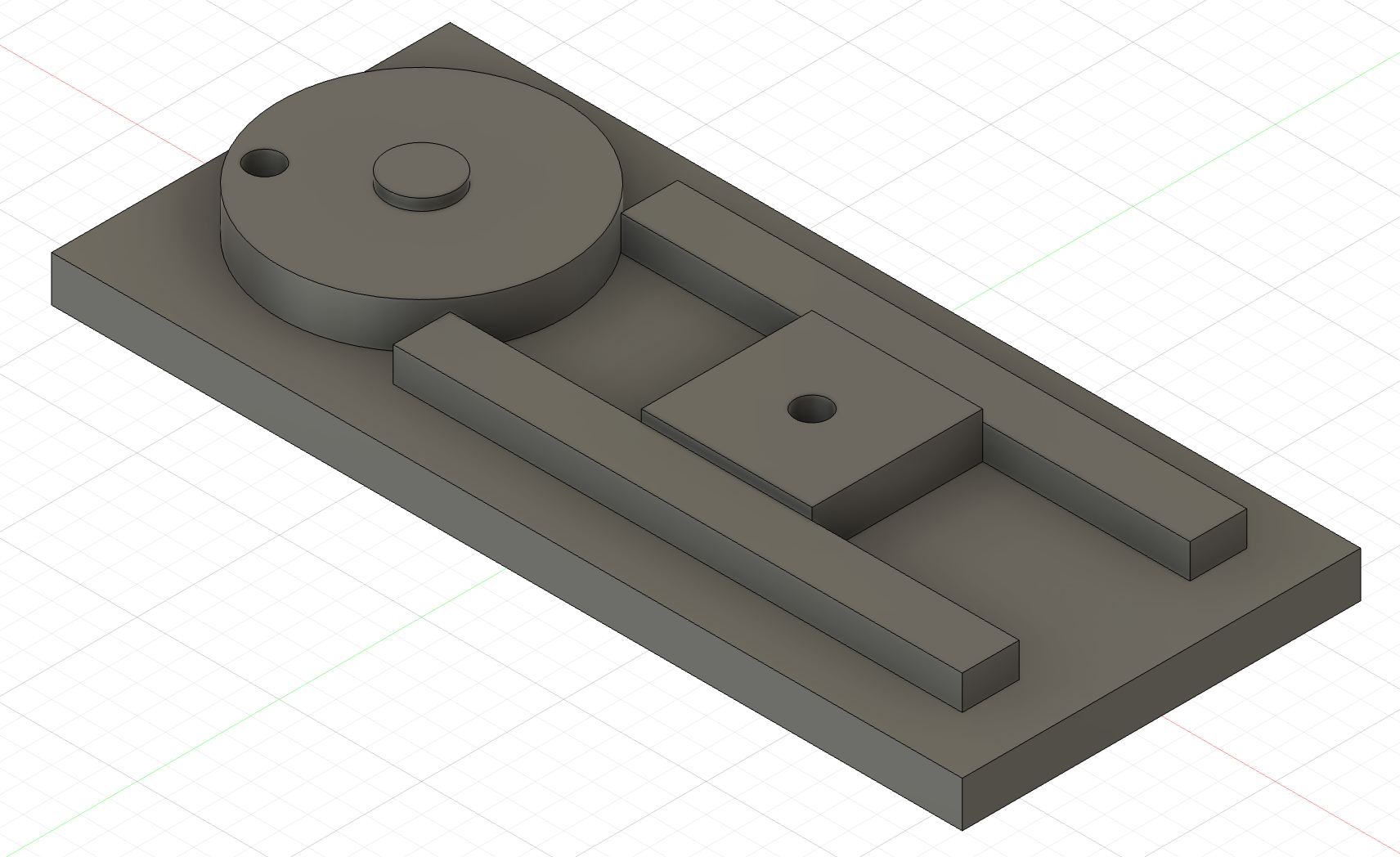
We could also set joint limits to control how far the Slider can slide, but the connecting rod will handle that in the next section.
Connect the Connecting Rod
These last two steps each bundle a few joints you already know how to make. Two Pins go in first, then the rod rides on them.
-
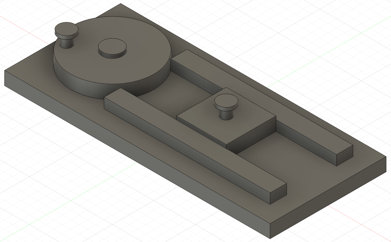
Add two copies of the Pin to your design, and create rigid joints to insert one in the Crank's outer hole and one in the Slider's hole, so that the bottom of each Pin is even with the bottom of the part it's inserted in. Name the joints Pin-Crank and Pin-Slider and hide them.
Stuck? Open for a hint.
Hide the Base as needed. Connecting a Pin to the Crank or the Slider works just like connecting the Axle to the Base: the bottom edge of the Pin to the bottom edge of the hole, then Rigid. You can insert the same part file as many times as you need, and each copy becomes its own component (Pin:1 and Pin:2).
-
Add the Connecting Rod to your design. Use revolute joints to attach the edge of each hole on the rod's top side to the underside of the head on each Pin. Name the joints Rod-Crank and Rod-Slider and hide them.
Checkpoint
The assembly is complete. Drag the Crank, the rod, or the Slider with your mouse, and the whole mechanism should move together: the Crank turns, the rod follows, and the Slider runs back and forth between the rails.
Go Further
Try these on your own once the mechanism runs.
- Drive it. Select Motion ▸ Drive Joints, pick the Crank-Axle joint,
and type
360 deg. Fusion turns the crank one full revolution for you, which makes a better screenshot than your mouse ever will. - Set a limit. Edit the Crank-Axle joint (right-click it in the Browser), and on the Motion tab set a minimum and maximum rotation. Watch what the limit does to how far the Slider travels.
Turn It In
- Your
Slider Crankassembly saved in yourSlider Cranklab folder, in your Fusion student folder, with thePartsfolder beside it. It's on Autodesk's cloud, so saving is submitting. - A notebook entry titled Assemblies and Joints with a screenshot of your finished assembly and its seven named joints visible in the Browser.
How It's Graded
This lab is worth up to 4 points. One score covers everything you turn in.
| Score | What it looks like |
|---|---|
| 4 — Excellent | The lab folder holds the assembly with its Parts folder beside it; all seven components are in the assembly with only the Base grounded; all seven joints use the right type and are named for the parts they connect; the mechanism runs when the crank is dragged; the notebook entry has the screenshot. |
| 3 — Above Average | The mechanism runs, with a slip: an unnamed joint, the assembly saved inside Parts instead of beside it, a Pin that sits proud of its hole, or a screenshot that doesn't show the Browser. |
| 2 — Average | The assembly is complete but doesn't run (a joint of the wrong type, or a second grounded part), or the connecting rod is missing. |
| 1 — Below Average | A few parts inserted with one or two joints, or a screenshot with no saved design behind it. |
| 0 — Failing | No Slider Crank assembly in your student folder and nothing in the notebook. |