A Useful Binary Computer: The Full Adder and a 4-Bit Adder
Your half adder can add two bits. That's a start, but real numbers have more than one digit. In this lab you'll build an adder that can pass a carry from one column to the next, then chain four of them into a circuit that adds real binary numbers — the arithmetic heart of a computer.
Overview
You'll build a full adder from two half adders and an OR gate, then chain four full adders into a 4-bit adder and test it, including the case where the answer is too big to fit — overflow.
Before you start
Open Antares with your HA (half adder) and MyOR gate available.
You've got it when…
- Your full adder gives the correct
SUMandCoutfor all eight input combinations. - Your 4-bit adder correctly adds two 4-bit numbers.
- You can show it handling a no-carry sum, a sum with carry, and an overflow.
Collaboration & AI
Work: On your own. A neighbor can help you untangle wires; the design is yours.
AI — AIAS Level 1, No AI: Build and test the adder yourself. What the levels mean.
The Plan
Your half adder gives you a Sum and a Carry (which shows the sum overflowed into the next column). A full adder does the same, but it also accepts a carry-in from a previous addition.
- Half adder — adds 2 bits (no carry-in).
- Full adder — adds 3 bits (two inputs plus a carry-in).
Today you'll build a full adder that handles one column plus a carry-in, then chain them to add multi-digit binary numbers.
Building the Full Adder
Complete the truth table for the full adder based on the description above.
Full Adder
| A | B | Cin (carry-in) | SUM (A+B+Cin) | Cout (carry-out) |
|---|---|---|---|---|
| 0 | 0 | 0 | ||
| 0 | 0 | 1 | ||
| 0 | 1 | 0 | ||
| 0 | 1 | 1 | ||
| 1 | 0 | 0 | ||
| 1 | 0 | 1 | ||
| 1 | 1 | 0 | ||
| 1 | 1 | 1 |
Follow these steps to build it:
- Create a new circuit named
FA(full adder). - Add three Circuit Inputs and rename them Cin, A, and B.
- Insert two of your
HA(half adder) components. - Insert your
MyORgate. - Add two Circuit Outputs and rename them SUM and Cout.
- Arrange and connect the components as shown below.
- Test the full adder in simulation for every row of the truth table.

Building a 4-Bit Adder
Now that you have a full adder — a component that adds two bits plus a carry-in — you can build a circuit that adds multi-bit binary numbers. We'll add two 4-bit numbers.
- Create a new circuit named
4-bit Adder. -
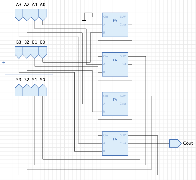
Add 8 Circuit Inputs and 4 Circuit Outputs. Rename and arrange them as shown, leaving room between the rows for wiring. Use the Text tool for the plus sign and the Polyline tool for the line.
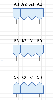
-
Add four of your
FAcomponents in a vertical row to the right, with some space between them.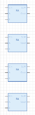
-
Starting from the top, connect the carry-out of each full adder to the carry-in of the next.
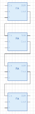
-
Connect each A input to the A input of a full adder.
Warning
These must be in order —
A0to the topmost full adder. Take your time and tidy your wires.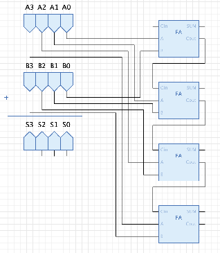
-
Do the same with the B inputs.
Warning
Again, in order —
B0to the topmost full adder.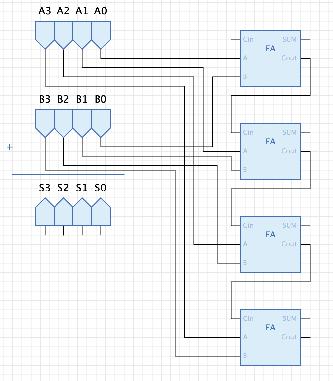
-
Connect the sum (
S) outputs to the FASUMoutputs the same way —S0to the topmost full adder.
-
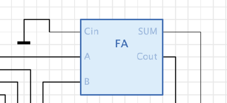
There is never a carry-in to the first full adder. Connect its carry-in to Ground (from the Net folder) to hold it at zero.
-
Add a final Circuit Output named Cout to the carry-out of the last full adder. It signals when a sum is too big for 4 bits.
Your finished circuit should look like this.
Turn It In
Develop a test plan and submit one screenshot of your simulation for each of these conditions:
- Two numbers where no digit requires a carry.
- Two numbers where at least one digit requires a carry.
- Two numbers whose sum is too large for 4 bits (overflow).
How It's Graded
This lab is worth up to 4 points. One score covers everything you turn in.
| Score | What it looks like |
|---|---|
| 4 — Excellent | The full adder matches all eight rows of its truth table, the 4-bit adder adds correctly, and your three test screenshots genuinely exercise all three conditions — with the binary sums you expected written in your notebook so the evidence checks itself. |
| 3 — Above Average | Both circuits work and all three tests are submitted, with a minor gap — a test case that doesn't quite isolate its condition, or one truth-table row wrong. |
| 2 — Average | The full adder works but the 4-bit adder has a wiring fault (crossed input order, missing ground on the first carry-in), or tests cover only some of the three conditions. |
| 1 — Below Average | The full adder doesn't match its truth table, or the 4-bit adder was not attempted, or no test evidence was submitted. |
| 0 — Failing | Nothing turned in, or no evidence of either circuit. |