sk8board Time!
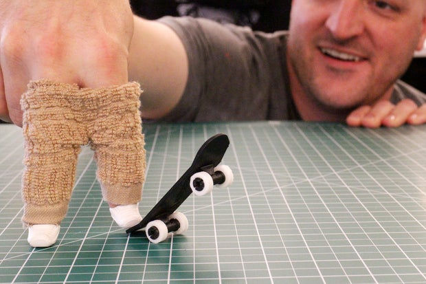
Let's design and 3D print a fingerboard — a tiny skateboard we can skate with our fingers! We'll program it so that we can customize some of its features.
Overview
This build has more parts than the bubble wand: axles, trucks, a deck with curved kicks, and wheels that print separately and snap on. We'll build it the same way real products get built — one small piece at a time, checking the model after every few blocks. Each step adds only the blocks shown in that step's picture, so if your screen matches the picture, you're on track.
Builds on: Bubble Wand —
you'll reuse variables, math blocks, Copy, Group Selection, and exporting
to .STL.
You've got it when…
- Your model has two complete axle-and-truck assemblies, a deck with a kick at each end, and four separate wheels.
- Your six variables control the board's dimensions.
- Your design is exported as an
.STLfile and submitted.
Collaboration & AI
Work: On your own. Ask a neighbor for a hand if you're stuck, but build your own board.
AI — AIAS Level 1, No AI: Building each piece yourself is how the blocks become yours. What the levels mean.
Add blocks — don't rebuild ones you have
Each block picture in this lab shows only the new blocks for that step, joined to the bottom of your program. When a step says to Copy, there is no new shape to drag in — the Copy block does the building. If your program grows two of something, you built a piece the lab meant for you to copy. Find the last step where your model matched the check picture and fix from there.
Create the Project
-
Go to the Tinkercad website, sign in, and create a new Codeblocks design.
-
Click the random name at the top of the screen and rename your project sk8board.
Variables
Real skateboards are described by their dimensions — how long the deck is, how far apart the wheels sit. Our six variables hold those dimensions, so at the end you can restyle the whole board by changing a few numbers.
-
Create these six variables (Math section ▸ Create number variable…): width, deck length, kick length, wheelbase, wheel outer diameter, and wheel inner diameter.
-
Drag a Comment block to the workspace so future-you remembers what this section is for.
-
Add six Set blocks and set each variable to the value shown.
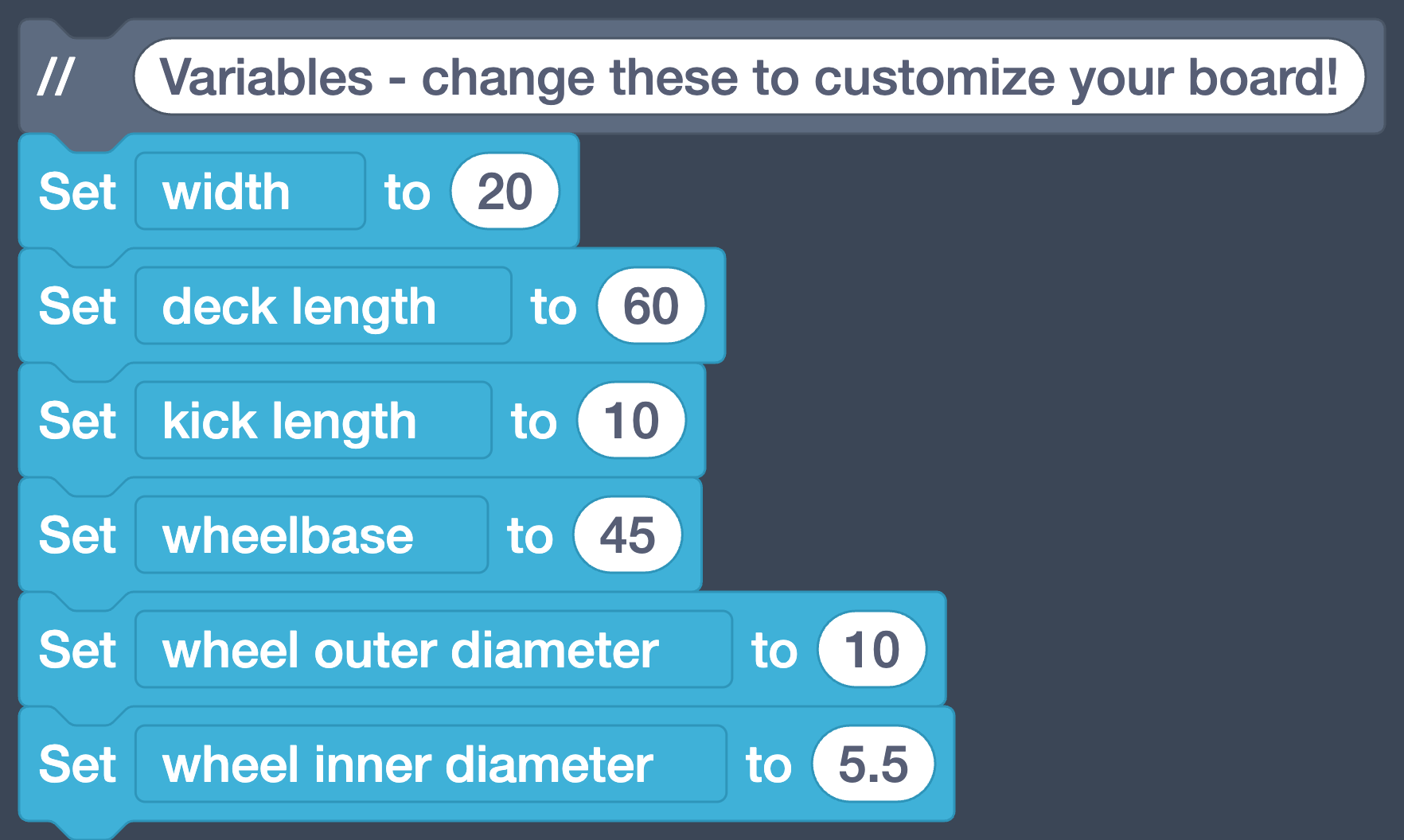
Here's what they will do:
- width will be the width of the skateboard
- deck length will be the length of the flat part of the deck
- kick length will be the length of the curved nose and tail of the deck
- wheelbase will be the distance between the wheels from front to back
- wheel outer diameter and wheel inner diameter will control the size of the wheels
Note
Click Play and… nothing appears. That's right — variables only store numbers. The Workplane stays empty until we add a shape.
The Wheel End
Axles are what the wheels spin on. Trucks mount the axles to the skateboard. We'll build these as one piece, starting with the end of the axle: two rings that a wheel will snap on and ride between.
Which way is up?
We build this board lying on its side — the axles stand upright and the deck will stand like a wall. It looks odd on screen, but the 3D printer doesn't care which way up a model was drawn, and building this way keeps every move and copy simple.
-
Start the section with a Comment block: Trucks and Axles.
-
Add a Torus with Radius 7, Sides 48, Tube 2.5, and Steps 24.
-
Add a Set size block with X 6, Y 6, and Z 2.
-
Add a Move block set to Z-axis max to
width / 2— this slides the ring out to what will become the edge of the skateboard.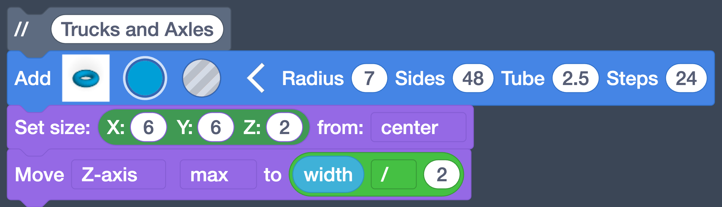
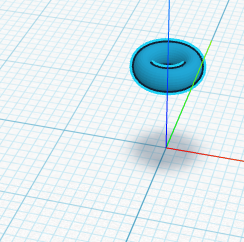
Run your program. Your model should look like this.
-
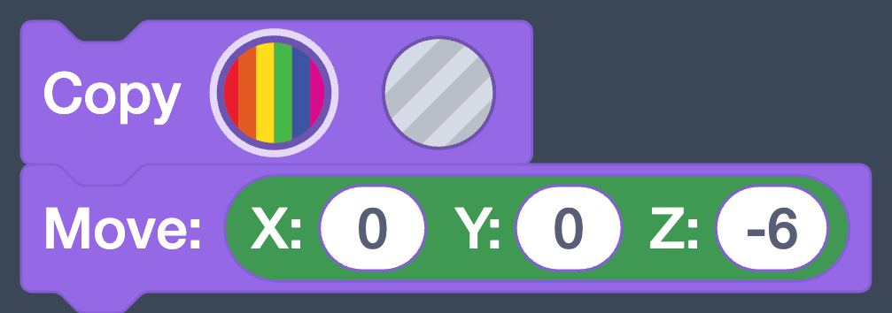
Add a Copy block to make a second ring from the first.
-
Add a Move block with X 0, Y 0, Z -6 to slide the copy down.
Your model should look like this.
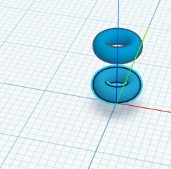
Why the gap?
The wheel will ride in the space between the rings — it snaps over the outer ring to get there.
The Snap Slits
A wheel snaps on more easily if the end of the axle can squeeze slightly. We'll cut an X-shaped slit into the axle end with two thin boxes — drawn now, but they only do their cutting later, when we group.
-
Add a Box with W 8, L 1, H 4, and Edge Steps 10 — and click the striped circle to make it a hole.
-
Add a Move block set to Z-axis max to
width / 2, moving the top of the box up level with the top ring.
Your model should look like this.
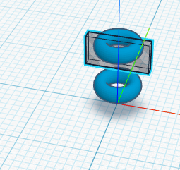
Why is it see-through?
Hole shapes stay ghostly until a Group Selection block tells them what to cut. Ours wait until the whole axle is built.
-
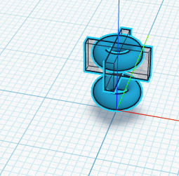
Add a Copy block to copy the box.
-
Add a Rotate around block: Axis z by 90 degrees, so the two boxes make an 'X'.

Your model should look like this.
The Other End of the Axle
Everything we've made so far is one wheel-end. An axle has two. Rather than build it all again — never build what you can copy — we'll copy the whole thing and swing it around to the other end.
-
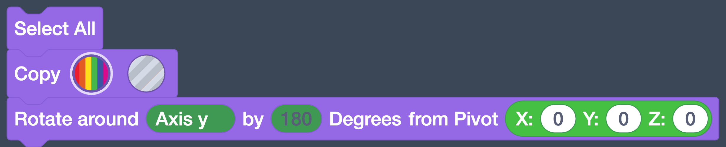
Add a Select All block.
-
Add a Copy block.
-
Add a Rotate around block: Axis y by 180 degrees, from Pivot X 0, Y 0, Z 0.
Where did the copy go?
Run your program — and it looks like nothing happened. Rotating from Pivot 0,0,0 spun the copy around the center of the Workplane, so the second wheel-end is now underneath the Workplane, mirroring yours. It's not gone; you'll see it swing into view when the axle is grouped and placed.
The Axle Itself
Now the bar that connects the two ends.
-
Add a Cylinder with Radius 2.5, H
width, and Sides 48 — the axle, running the full width of the board. -
Add another Cylinder with Radius 3.5 and H
width - 14— a thicker sleeve around the middle of the axle.
Run your program. This one is subtle: a thin rod now pokes up through the rings, and the thicker sleeve hides between the two wheel-ends (half of it below the Workplane). If you can see the rod, keep going — the next check makes everything visible at once.
The Truck
The truck is the mount between the axle and the deck. Ours is a triangle.
-
Add a Roof with L 20.
-
Add a Set size block with X 10, Y 4, Z 8.
-
Add a Rotate around block: Axis y by -90 degrees.
-
Add another Rotate around block: Axis z by 90 degrees.
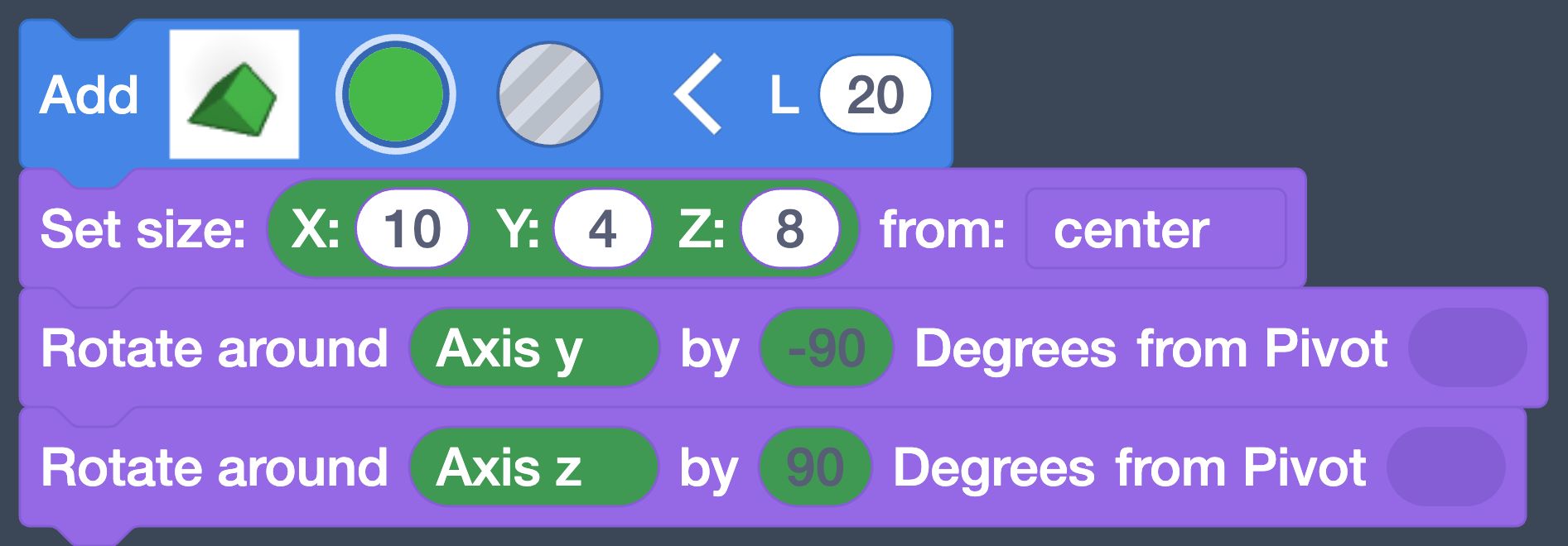
Your model should look like this — the whole axle at last: rings and slits at both ends, the orange axle and sleeve, and the little green truck triangle on its middle.
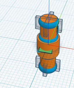
Group It and Put It in Place
Time to make it one piece and park it where the front axle belongs.
-
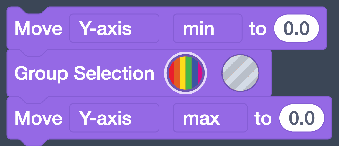
Add a Move block set to Y-axis min to 0.0.
-
Add a Group Selection block.
-
Add a Move block set to Y-axis max to 0.0.
-
Add a Move block with X set to the equation
wheelbase / 2 - 2, sliding the finished assembly forward to become the front axle.
Order of operations matters here
Build this equation as (
wheelbase / 2)- 2: dividewheelbaseby 2 first, then subtract 2 from the result. The blocks will happily snap together the other way —wheelbasedivided by (2 - 2) — but 2 minus 2 is zero, dividing by zero is undefined, and part of your model will simply vanish. If your axle disappears at this step, this equation is why. Match the nesting in the picture above exactly: the division block sits inside the subtraction block.Your model should look like this. Grouping is when the hole boxes finally cut their slits — the axle is now one solid piece, sitting forward of center.
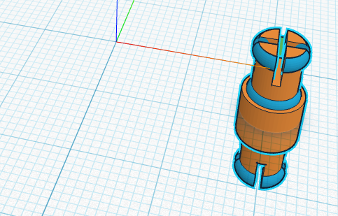
-
Add a Copy block — the whole front axle, copied in one block.
-
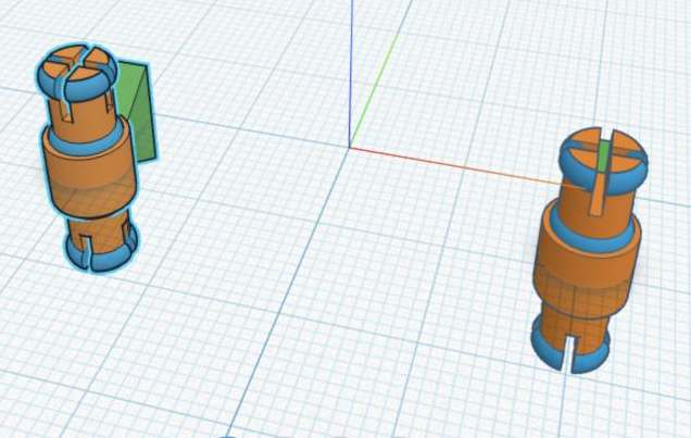
Add a Rotate around block: Axis y by 180 degrees, from Pivot 0, 0, 0 — the copy swings around the center to become the rear axle.

Your model should look like this.
Checkpoint
Two complete axle-and-truck assemblies — and you only built one. Count the wheel-ends on your screen, then count how many you actually built from scratch. (Four; one.) That's what Copy is for.
Day 2 starts here
Run your program. Your model should match the picture above — both axles, slits cut. If it doesn't, fix that first; today's deck lands on them.
The Deck
Now the deck, which is the part of the skateboard the skater stands on. Remember the board is built on its side, so the deck will stand up like a wall between your two axles.
-
Start a new section with a Comment block: Deck.
-
Add a Box with W
deck length, L 2, Hwidth, and Edge Steps 10. -
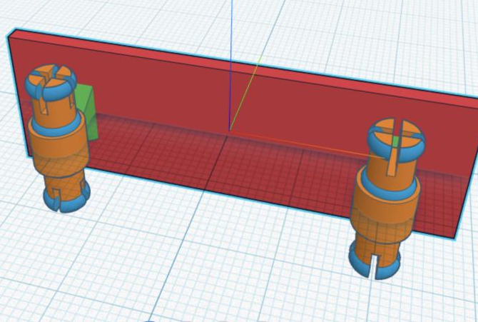
Add a Move block set to Y-axis min to 0.0, seating the deck against the trucks.

Your model should look like this.
The Kicks
A kick is the part of the deck that curves upward at the nose so the skater can pop tricks. We'll shape one, tilt it, and attach it to the front.
-
Start with a Comment block: Front Kick.
-
Add a Round Roof. In the picture its Add block is collapsed — the arrow on an Add block hides and shows its parameters, and this one keeps them all at their defaults.
-
Add a Rotate around block: Axis y by 90 degrees.
-
Add a Set size block: X
kick length, Y 2, Zwidth.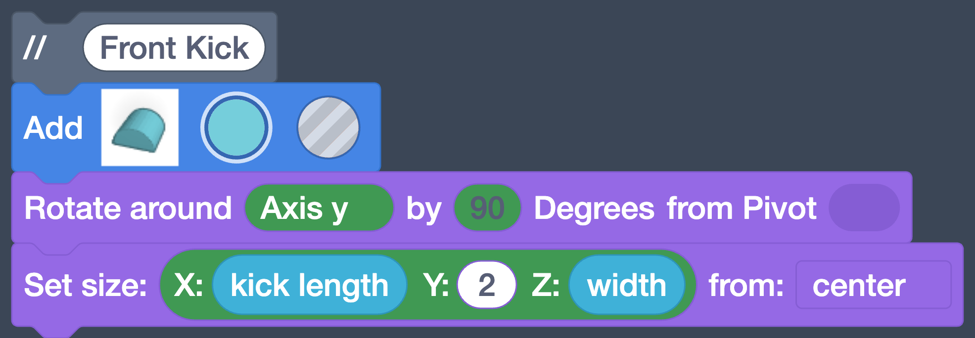
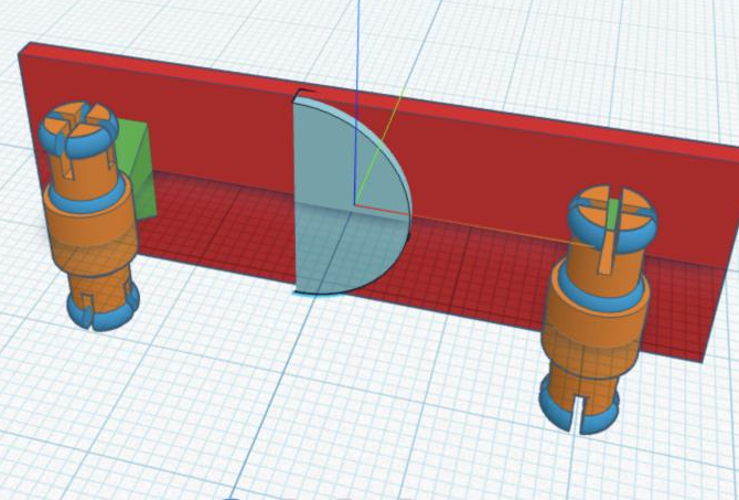
Your model should look like this — the kick is the thin arched piece standing at the center of the deck.
-
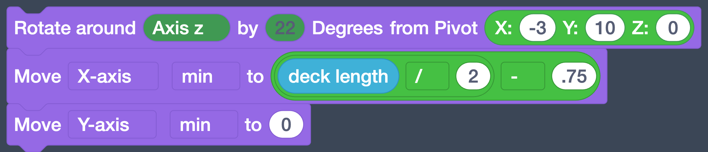
Tilt it: add a Rotate around block, Axis z by 22 degrees, from Pivot X -3, Y 10, Z 0.
-
Add a Move block set to X-axis min to the equation
deck length / 2 - .75, sliding the kick to the nose. Same equation shape as step 28 — divide first, then subtract, with the division block nested inside the subtraction block. -
Add a Move block set to Y-axis min to 0.
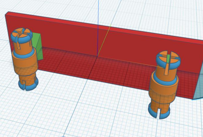
Your model should look like this. The kick is easy to miss now — it has tucked itself against the nose end of the deck, tilted to curve away. Orbit your view to the end of the board if you want proof it's there; the next step makes it obvious.
-
Add a Comment for the back kick — it's just a copy of the front kick, rotated around to the other side of the deck.
-
Add a Copy block.
-
Add a Rotate around block: Axis y by 180 degrees, from Pivot 0, 0, 0.

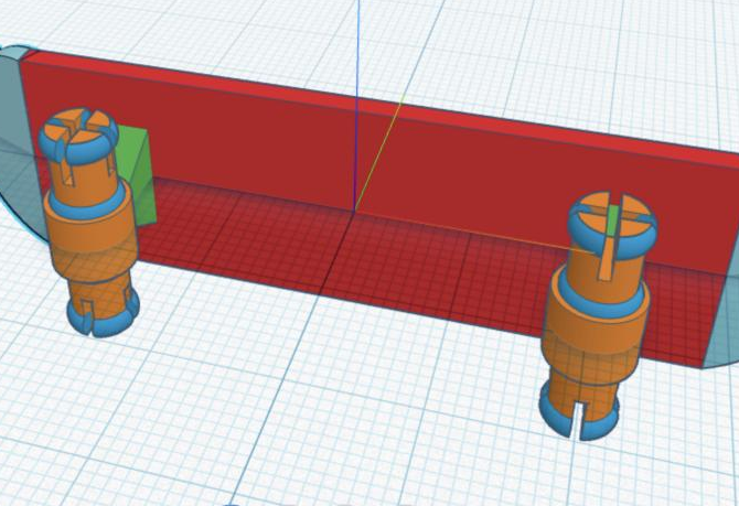
Your model should look like this — now a curved kick shows at both ends of the deck.
The Wheels
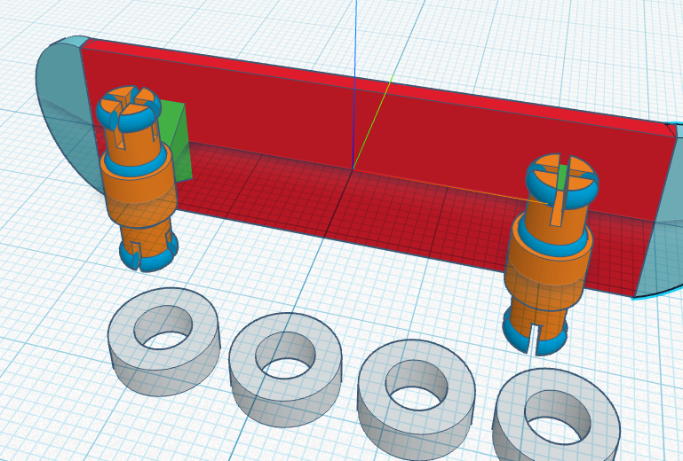
Finally, the wheels — four of them, printed as separate pieces beside the board so they can snap onto the axles and actually spin. Four identical parts is a job for a loop, like the ridges on your bubble wand.
-
Start the section with a Comment block: Wheels.
-
Add a Count with loop block, set to count with
ifrom 1 to 4 by 1. -
Inside the loop, add a Tube with Radius
wheel outer diameter / 2, Wall Thickness the equation shown (the difference between the two wheel diameters, halved), and H 3.5. -
Inside the loop, add a Move block with X set to the equation
i * 12 - 25and Y -20 — becauseichanges each time around, each wheel lands in its own parking spot. -
Inside the loop, add a Move block set to Z-axis min to
width / -2.
Your model should look like this.
Warning
The wheel sizes aren't decoration — the 5.5 inner diameter is what lets the wheel snap over the axle rings and spin. Change it without changing the axle, and the wheel won't fit.
Preparing for 3D Printing
We need to export our design in a format that the 3D printing software can use.
-
Click the Share button
 in the upper
right corner.
in the upper
right corner. -
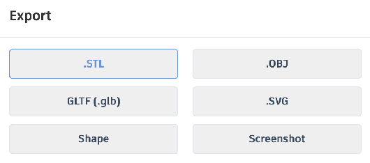
Select .STL
-
Submit your downloaded
.STLfile in Google Classroom.
Turn It In
- Your fingerboard's
.STLfile, submitted in Google Classroom.
Credit: Adapted and updated for Codeblocks from this tutorial.
How It's Graded
This lab is worth up to 4 points. One score covers everything you turn in.
| Score | What it looks like |
|---|---|
| 4 — Excellent | Your submitted .STL has both axle-and-truck assemblies with the snap-on slits, a deck with a kick at each end, and four separate wheels — and the six variables genuinely drive the design, so changing width or wheelbase rebuilds the board to match. |
| 3 — Above Average | A complete board is submitted with a minor mismatch — a kick rotated slightly off, a wheel overlapping an axle, or one dimension hard-coded where a variable belongs. |
| 2 — Average | Real gaps — one axle instead of two, no kicks, or missing wheels; or the variables exist at the top but the shapes below don't use them. |
| 1 — Below Average | A few shapes that don't yet resemble a skateboard, or nothing exported. |
| 0 — Failing | Nothing submitted and no design in your account. |